VAF Filtration System: V-Series Automatic Filter

V-SERIES AUTOMATIC FILTER
How It Works
Please refer to the cutaway of the “V” series filter shown.
Dirty water enters the filter through the inlet (1) and then passes through the coarse screen (2) from the outside in. It flows from the inside of the coarse screen to the inside of the fine screen and then passes through the fine screen (3) from the inside out. Dirt is collected on the inside surface of the fine screen. The clean filtered water then exits through the filter outlet (4) and on to the system.
As the dirt or cake builds up on the inside surface of the fine screen, the pressure drop across the screen increases. When the pressure drop (the DP or differential pressure) reaches a preset level 0.5 bar (7 psi), the filter controller starts a flush cycle by opening a flush valve on the flush line (5). This flush valve exhausts the drive chamber to atmosphere at “0” psi.

The flush line (5) is connected to the drive chamber which is separated from the filtration chamber by a drive chamber partition (6). However, the dirt collector (7) (a hollow pipe with dirt collector nozzles) extends through the partition (6), thus providing a “path” from the dirt collector nozzles (8) through the hydraulic drive (9), into the drive chamber and out the flush line (5) to atmosphere. The pressure around the dirt collector nozzle (8) is the pressure inside the filter and as water flows through the “nozzle orifice,” it drops to “0” psi when it leaves the flush line (5). This creates an aggressive “suction” at the dirt collector nozzle (8) opening. The dirt collector nozzle (8) clearance at the fine screen (3) is very small so the extreme low pressure at the nozzle opening creates a vacuum causing backflow to pull the dirt from the fine screen (3).
The hydraulic drive (9) has opposite facing jets near its ends. Water jetting out of these openings (coming from the dirt collector nozzles (8)) creates a reaction force (like a pin wheel) which rotates the drive (9) and the dirt collector (7). As the dirt collector (7) rotates, each dirt collector nozzle (8) cleans a band on the fine screen (3).
As the dirt collector (7) rotates, the reverser (10) (works like the level winder on a fishing reel) causes the hydraulic drive (9) / dirt collector (7) / dirt collector nozzle (8) assembly to move back and forth on a controlled path. This ensures proper overlap for 100% cleaning of the screen’s inner surface. The rotation governor (11) helps control the rotation speed of the dirt collector (7) assembly. The balance tube (12) helps balance the transverse pressure on the assembly. A magnet located on the end of the balance tube repels the reverser indicator (13) which provides visual indication of the dirt collector (7) assembly movement. This indicates that the entire cleaning system is operating properly during the rinse cycle.
After a preset time, the flush valve closes and the flushing cycle is complete. Very little water is used for each flush; the filter continues to supply water to the system during the flush cycle.

General Information
The V-Series™ design is the most recent, state-of-the-art self-cleaning screen filtration technology available today. The complexity and cleaning efficiency of any self-cleaning screen filter is in the mechanical system that drives the cleaning process. The V-Series patented Bi-directional Hydrodynamic Drive (BHD) mechanism is the simplest and most efficient in design resulting in:
- fewer moving parts (no limit switches or pistons reversing the cleaning mechanism),
- simpler controls,
- lowest flush flow available,
- greater cleaning efficiency, and
- lower maintenance requirements

The V-Series’ 12 to 15 second flush cycle is automatically initiated when a pressure differential across the screen increases to 0.5 bar (7 psi). The filter remains on-line and the filtration process remains uninterrupted during the brief cleaning process. The flush discharge is the lowest available resulting in minimal waste.
The V-Series filters are available in ASME code and are manufactured in an ASME facility. The filters are available in a broad range of materials, pressure ratings, and temperature ratings to suit any need. VAF custom manufactures filters and skids that simplify installation and meet specific requirements.

Materials
Filter body: 3” – 20” inlet/outlet, 316 SS
Screens: 316L SS sintered **
Flanges: AWWA Class D **
Seals: nitrile, viton, silicone **
Filtration Range: 10 to 1500 micron **
Flow Range: 7 to 1364 m3/hr (30 to 6000gpm) per filter *
Max Pressure: 10 bar (150 psi) **
Min Pressure: 2 bar (30 psi) **
Max Temp: 80° C (176° F) **
Flush Cycle: 12 to 15 seconds
Controller: MicroFlush – up to 4 filters
* Varies depending on micron level.
** Other options are available on request.
For more information contact:
Conservation Solutions
978-266-1900
info@ConservationSolutions.com
Recent News
Water Use – Are Your Water Costs Out of Control?
Conservation Solutions is highly effective in designing water efficiency programs tailored to meet your budget. We take a comprehensive look at opportunities to reduce water use by increasing efficiency. We work closely with customers to dramatically reduce water use in buildings by identifying and installing state of the art technologies that best meet the unique needs of your building or facility.
Air Quality and What You Don’t Know
Hospital Acquired Infections (HAIs), the Human cost of poor indoor air quality (IAQ), Odors, Energy Losses from poor heat transfer surfaces and reduced air circulation.
Water Resources: Why Water Conservation & Water Efficiency is Important
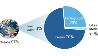
Le Monde diplomatique: Water stress is defined as having a high percentage of water withdrawal compared to total available water in the area Water: Only 3% of water on earth is fresh water. 70% of the fresh water is lockedup in ice caps and glaciers. Only 1% of the...


